Happy New Year (2024) lets hope its a healthy one along side some nice flying weather, we can only keep our fingers crossed !!!
Annual Membership Fee’s
A reminder that if you have not paid yet time is running out for the early payment reduction scheme.
You can pay via the club website and then bank transfer or the monthly payment scheme which Mark Conlin can set up for you.
The club will not come chasing you for payment its up to yourself to pay your fees if you want to continue flying this year.
Quiz Night and Hotpot Supper
The last indoor event of 2023 was the annual quiz and hotpot supper. Once again it was a great evening with the normal barracking of the quiz master. Clive Myrie would not put up with such behaviour !!
I have forgotten who actually won but everybody got a prize kindly donated by Jake Reid.
Below are some photos of the evening


By the way the hotpot was fantastic Justin
First Indoor Meeting 2024
The first indoor meeting of the year took place on Wednesday 3rd January and was titled ‘What Santa Bought You’
I was not at the meeting so cannot report on what people brought along to the meeting.
I have been made aware though of a fancy device for working out the C of G of a model plane which Jason brought along. The system is made by SkyRC and I have personally seen it before at a show.
Richard Cuthbert was very impressed with system but went home thinking if similar results could be obtained via a cheaper less complicated set up.
Richard has very kindly written up his thoughts and results, the report is contained below.
Model Aircraft Centre of Gravity
Whenever we make a new model, it is usual to check that the Centre of Gravity (CG) is in the correct place. A simple rule of thumb is that if it balances on our fingers at about 25 – 30% of the wing chord it should be ok. However, large models and those with more exotic wing shapes and configurations can make this more difficult and any of us who have tried to fly a model that has a CG too far aft, tend not to want to repeat the experience. So, a more direct measurement method of finding the actual CG of a model is sometimes a good idea.
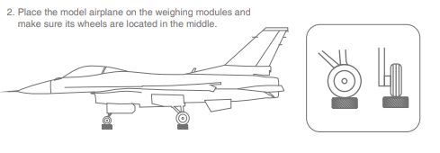
At the last “what did Santa bring” Club meeting in January, Jason Reid demonstrated a very impressive piece of kit to do just this job. It consisted of 3 weighing “modules”, which were placed under each of the U/C wheels. They were wirelessly linked to a mobile phone, with an app which gave a readout of where the CG was based on the relative weights measured at each pad.
Further details and the specification for this type of device can be found at:
This system included numerous design features to ensure accurate and repeatable measurements. In operation, it worked very well giving instant results. It also indicated how much additional weight should be applied at what point, to shift the CG to the desired position. As it measured the weight on both front wheels, it could also identify if the CG was off-centre laterally, should it need correction.
In the demonstration, Jason made the point that for best accuracy, the model must be level when measurements were carried out. To make levelling as easy as possible, an Angle Sensor was included in the kit. This gave a complete test system capability, that could give a highly accurate CG position and correction information in real time.
As without such an angle sensor it is quite difficult to determine precisely whether a model is “level”, this prompted a (lively) discussion on how much the results might be affected if the model was not truly level.
After seeing how easy it was to obtain these CG results, it prompted some other thoughts after the meeting:
- Could these principles be used to give an acceptable indication of CG position with less sophisticated equipment?
- If so, how sensitive would the results be to tilt angle errors?
- How could we improve measurement accuracy?
- How accurate do CG measurements need to be?
- Could we predict how much ballast needs to be added/moved and where?
This note is aimed at addressing these questions.
The Measurement Method
The set up demonstrated by Jason was a level aircraft, supported on the three weight measurement pads:

In this diagram the key parameters are:
Wfront = Weight of both wheels on the front weighing modules
Wtail = Weight on the tailwheel
L = Horizontal distance between wheel axles
X = Horizontal distance between front axle and CG position
From these measurements the horizontal distance from the front axle to the CG position (X) can be calculated by the formula:
X = Wtail x L / Total Weight
This shows that we can find CG position along the fuselage if we know the total weight of the model and the weight on the tail wheel. This means that this method should be possible using just a single weighing scale.
Note however, that “X” is the distance from the axle centre to the CG, not LE to CG as it is normally specified. The horizontal distance between the LE and the front axle needs to be subtracted from “X” to find the LE/CG distance.
A standard digital weighing scale was used to measure the weight under the tailwheel of a WOT 4E model – as level as possible by using a straight edge on the elevator – and then the CG position was calculated, using this method.
The CG calculation for the WOT4E came out at 79mm from the LE. The recommended position is 80mm from the LE.
How Level Does the Model Need to Be?
If the CG position is marked on the side of the fuselage and the front wheels fixed in position, the CG can be seen to move relative to the front wheels’ contact point on the ground, as the tail is lowered or raised. This is due to the CG being above and behind the front wheel contact point.
This is shown in the diagram below:

When the tail is lowered, as the CG moves backwards relative to the front wheels, weight will be shifted towards the tail wheel. This is exactly what Jason demonstrated with his WOT 4 at the meeting – the weight on the tail wheel increased as he lowered the tail.
If the formula above uses these new weight values – which assumes that the model is level – it will predict a CG further back than it really is.
Conversely, if the model is tilted forwards, the CG will be predicted to be further forward than the actual value. The worst case is when the model is tilted so far forward that the CG is over the front wheels (about 20 degrees on the WOT4E). There would be zero weight on the tailwheel in this condition and the calculated wheel/CG distance would equal Zero.
Based on theoretical predictions, the effect of tilt on CG position of a WOT4E, around the fuselage level position was calculated as follows:
| Angle (Deg) | CG (mm) | Error (mm) | |
| Forward | 3 | 69 | -11 |
| Forward | 2 | 73 | -7 |
| Forward | 1 | 76 | -4 |
| 0 | 80 | 0 | |
| Back | 1 | 83 | 3 |
| Back | 2 | 85 | 5 |
| Back | 3 | 88 | 8 |
As a comparison, tests using the weight measurement method described above gave very similar changes in tail weight and CG position.
As can be seen from the table, the errors become slightly worse when tilted forwards. Therefore, it would seem sensible to err on the side of being tilted backwards, when carrying out any measurements.
For reference, raising or lowering the tail by 10mm on a WOT 4E is about 1 degree of tilt. This would mean that to get the CG distance accurate to within +/- 3mm, the tail needs to be within +/- 10mm of being perfectly level.
The errors are driven by the height of the CG above the front and rear wheel contact points, relative to the model size. In the case of the WOT4E, the tail wheel height is small, so the errors are dominated by the front U/C height. A model with similar geometry to a WOT 4E would have similar error characteristics. With a tricycle U/C, both front and rear legs are of similar height, so the errors are about 10% larger.
As a rule of thumb, the error in CG for models per degree around the level position is
CG Error = CG to wheel contact height / 60
This should scale directly for all sizes of models.
It is also worth noting for all types, the bigger the wheels used, the CG position errors will be slightly reduced.
Improving Accuracy
Because of the sensitivity to U/C height, the most obvious step to reduce the errors would be to support the body as close to the longitudinal axis of the fuselage going through the C of G as shown in the diagram:

If the actual CG lies along the line between the two support points, the error due to any tilting of the fuselage would be zero. Something close to this could be achieved by supporting the fuselage at the spinner centre and measuring the weight under the rear stabiliser.
A practical solution might be to hang the model from these points and measure the weight at the tail with a spring (tension) balance. This would be similar to the approach that Mark Conlin described at the meeting, of hanging a large model by a cord (passed over a pulley) attached at the two extremities. In his method, the model “settles” when the pulley is directly over the CG.
To verify this the WOT4E was suspended by a piece of string underneath the motor shaft and the weight at the tail measured underneath the stabiliser. The tail weight varied by no more than 2 g over at least +/-5 degrees. This small variation would be because the actual vertical position of the CG did not lie precisely on the motor shaft to stabilizer line.
With these measurements, the calculated CG position was 80mm from the LE, with a variation of only 1.5mm over the +/-5 degrees of tilt. This is almost an order of magnitude more accurate than measuring using the undercarriage.
This method could also be used for models without an undercarriage.
Finally, errors may creep in when measuring both weight and distance between weighing points. Most affordable weighing scales should be adequate as they usually measure to within 1g. Providing the vertical datums for length measurements are set with care (using a set square?), length measurements should be accurate to within a few mm. Only for the very smallest models might these errors become significant. In these cases (such as EEK!!), other CG measurement solutions might be more suitable (balance points under the wing?).
How Accurate Does the CG Position Need to Be?
Unless using an own design, most models have a recommended CG position. This is usually sufficiently conservative for stable flight. Depending on their confidence and skill, the pilot can then experiment to get the sweet spot for the particular model. There is nothing to beat skill and experience in knowing how far you can deviate from the “as designed” CG.
But what about unusual configurations? Deltas with canards etc.
There are many “CG calculators” free on the internet to calculate the “required” CG position, which cover most configurations. A typically flexible example can be found at:
https://rcplanes.online/cg_calc.htm
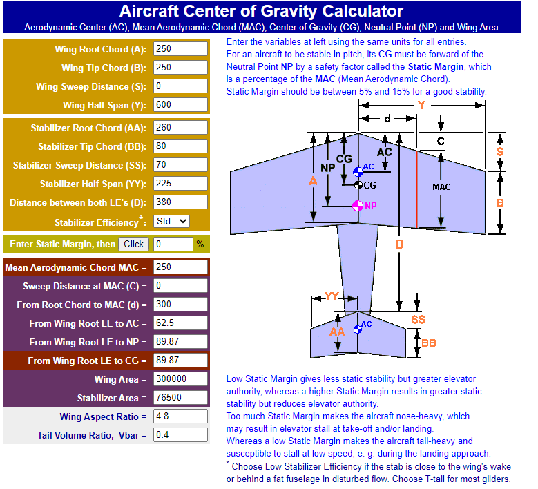
The calculators generally need to know what level of inherent stability the pilot wants for the model. This is input as a “static margin”, which determines the position of the CG along the Mean Aerodynamic Chord (MAC).
The normal range for static margin is between 5% (CG back – for a “lively” model) and 15% (CG forward).
Using the geometry of the WOT4 E, the recommended CG position of 80mm from LE gives a static margin of 3.5%, which was slightly less than expected as it is quite a stable aircraft in practice. The much more conservative 15% was 18mm further forward.
Where the calculator can be quite useful is when the static margin is set to 0%. This gives the CG position at which the model becomes unstable – a useful indicator of when a maiden flight might become a little more exciting than desired. The calculator predicted that this “limit” for a WOT 4E was 90mm – 10mm behind the recommended position of 80mm.
This gives a CG window of 28mm between a flyable but sluggish WOT4E model and one that is unstable. This would indicate that, providing the CG setting for initial flight was set at around the mid point of this 28mm range, tilt errors of +/- 2 degrees in measuring CG position via the U/C, would still be in the acceptable range. If in any doubt, another reason for tilting the fuselage slightly backwards during measurement is that it gives a “pessimistic” (rearward) value for CG position.
Moving CG to a Target Position
The usual method for moving a CG to a desired position is by the addition of ballast to a specific position. An alternative is to move an existing heavy component (motor, battery, fuel tank etc.) to a new position.
Similar calculations can be used to predict the effect of these changes on the CG, which could be a useful tool if these modifications are to be included during build.
Conclusions
The CG Tool that Jason demonstrated provides a very capable and convenient method to determine a model’s CG position and how to move it to a desired point.
A similar approach is viable using a single weighing scale, albeit with lower accuracy.
The sensitivity to tilt errors of this approach is significant, but with a careful test set-up should be within acceptable bounds.
If there is doubt over whether a model is level during measurement, it would be best to err on the side of a backward tilt.
If a really accurate result is required, a modified measurement method can be used. This will also cater for models without an undercarriage.
I hope that this note has been useful, if only to assist those who normally suffer from insomnia.
If anybody would like any further information, such as the changes in the calculations for a tricycle U/C, or those for moving the CG, please contact me.
The committee members for next year (2024) are as follows
Jason Reid Chairman
Mark Conlin Vice Chairman & Treasure
Dave Hindley Secretary
Andy Harrison Membership Secretary
Jake Reid Events Secretary
Anthony Ollerton Safety Officer
Andy Moore Committee Member
Duncan Melvin Committee Member
Steve Warburton Committee Member
Tim Fairhurst Committee Member
Please support the above members in their tasks wherever possible
Regards Chris V